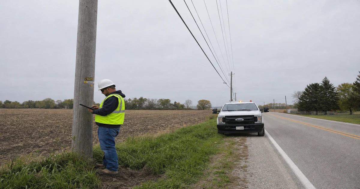
Before a single fiber route gets designed, someone has to go look at the poles. That sounds obvious. It isn't — not to everyone. I've seen ISPs hand an engineer a county GIS export and a Google Maps link and tell them to start design. The resulting LLD package usually falls apart somewhere between the make-ready application and the first construction crew call. The poles are wrong. The loading data isn't there. The span lengths don't match. The whole thing goes back to the field anyway, only now there's a schedule cost on top of it.
Strand mapping and aerial plant assessment are how you avoid that. Done right, a field survey gives your engineering team the verified, attributed spatial data they need to start LLD design with confidence. Done poorly — or skipped — it pushes every problem downstream where it costs more to fix.
This guide covers what the process actually involves: what data gets collected, why desktop sources don't substitute for field verification, how different survey methods compare on cost and accuracy, and what a deliverable that an engineer can actually use looks like. We'll also walk through the specific gaps that cause rework — based on what we see repeatedly in the field across our active deployments.
What Strand Mapping Actually Is
A strand map is a spatially accurate record of aerial infrastructure along a proposed fiber route. It captures the physical state of every structure — pole location, height, class, existing attachments — and the spans between them: strand gauge, sag, tension, and clearances. The output is a GIS dataset, not a sketch. It's the baseline document that makes everything else in the design-to-build workflow possible.
The term gets used loosely. Some people call any route diagram a "strand map." That's not accurate. A real strand map has verified pole IDs tied to the utility's asset records. It has measured attachment heights — not estimated, not pulled from a database, measured. It has GPS coordinates accurate enough to match field conditions. Without those attributes, what you have is a line on a map, not a usable engineering dataset.
Why does it matter before fiber design starts? Because OSP engineering decisions depend on it. Where you place your lashing wire, whether you need a pole replacement, whether a span requires mid-span support — none of that can be determined responsibly without verified field data. Engineers who work from unverified GIS are essentially guessing at structure conditions. Some of those guesses fail at the make-ready stage. Others fail in the field.
Strand mapping is the first step. Not an optional one.
Strand Map vs. Pole Inventory: Not the Same Thing
These two terms get conflated constantly, and the confusion causes real problems when ISPs scope their survey work.
A pole inventory is a record of poles as structures — owner, class, height, install year, condition, GPS location. It answers the question: what poles exist, and what condition are they in? Utilities and municipalities maintain pole inventories. Some are reasonably current. Many aren't. A pole inventory alone tells you nothing about what's attached to those poles, what the span geometry looks like, or whether the existing loading leaves room for your fiber.
That's where a strand map — or aerial plant assessment — goes further. It records what's on the poles and between them. Every attachment by owner. The height of each attachment from the ground. Span lengths. Strand gauge and wire type. Sag percentage at the midpoint. Anchor locations and condition. Clearances — over roads, over driveways, near buildings. That's the data that drives make-ready engineering and pole loading analysis. You can't run a loading model on a pole inventory. You need the attachment data that only a field assessment provides.
On a project we completed in eastern Tennessee — 312 poles across 8.3 miles of rural county road — the utility's pole inventory was only 74% accurate against what our crew found in the field. Twenty-three poles had been replaced and renumbered without the GIS record being updated. Eleven had decommissioned attachments that still showed as active. Six poles on the inventory didn't exist anymore — removed after a storm, never cleared from the database. If the engineering team had used that inventory as their baseline, they'd have built a loading analysis on data that was wrong for 22% of the route.
What an Aerial Plant Assessment Collects
A complete aerial plant assessment collects data in two categories: per-pole attributes and per-span attributes. Both are required for LLD and make-ready engineering. Missing either category produces an incomplete dataset that will require return trips or engineering assumptions — and engineering assumptions on loading data are a risk no responsible engineer should be asked to take.
Per-Pole Data
- Pole ID — verified against the utility's pole tag or branded number, not estimated from a GIS export
- Pole owner — primary owner and any joint-use owners
- Pole class and height — as measured or verified from the pole tag
- GPS coordinates — sub-meter accuracy preferred; 1.0m maximum for production-quality work
- Existing attachment heights — by owner, measured with laser height meter, not estimated
- Existing loading count — total number of current attachments
- Anchor rod condition — present, absent, visible corrosion, angle
- Down-guy and stub-pole conditions — especially at corners and dead-ends
- Photo documentation — minimum one photo per pole, more at conflict points
- Condition notes — lean, rot, damage, insulator condition
Per-Span Data
- Span length — measured or calculated from verified pole GPS coordinates
- Strand gauge — identified from visual inspection or utility records
- Sag at midspan — measured or estimated from field observation; 14.2% sag on an unreinforced span is a flag for loading review
- Clearance over road crossings — measured height above road surface at midspan
- Clearance over driveways, structures, waterways
- Any special conditions — high-tension spans, underbuild conflicts, railroad crossings
Good field survey data accuracy requires that attachment heights be measured — not read from a database — and that GPS positions be collected with a calibrated device, not auto-populated from a county GIS layer. This distinction matters more than most ISPs realize until the first permit rejection comes back citing clearance violations.
Survey Method Tradeoffs: Walk, Drive-By, LiDAR
There are three primary methods for conducting a strand mapping or aerial plant assessment, and they don't produce equivalent results. The right choice depends on route length, terrain, required data fidelity, and budget. Here's how they actually compare:
| Method | Typical Cost | Data Fidelity | Best Use Case | Key Limitations |
|---|---|---|---|---|
| Walking Survey | $47–$85/pole | High — measured heights, verified IDs, close-range photo | Make-ready engineering, dense attachment zones, permit-sensitive routes | Slowest method; 1.5–3 hrs/mile; access-dependent |
| Drive-By Survey | $18–$32/pole | Medium — GPS positions accurate, attachment detail limited at height | Preliminary route scoping, low-density rural routes | Can't verify attachment heights or pole IDs reliably; misses anchor/down-guy conditions |
| Mobile LiDAR | $9,000–$22,000/mile (setup + processing) | High for geometry — span length, sag, pole positions; lower for pole ID and attachment owner | Long routes (15+ miles), BEAD-funded projects requiring full route capture, repeat surveys | Requires ground-truth validation; post-processing adds 3–5 business days; doesn't capture pole tags |
Walking surveys are the standard for make-ready work. If a route has attachment conflicts, tight clearances, or poles with heavy existing loading, walking it is the only way to get reliable data. Drive-by is acceptable for a first-pass scoping exercise — to estimate pole count or flag obvious problem areas — but don't use it as your engineering baseline. You'll pay for the shortcut in rework.
LiDAR is genuinely useful on large projects. On a 27-mile route in northwest Ohio, we used vehicle-mounted LiDAR for the full corridor and then deployed a walking crew to 94 flagged poles where attachment conflict was anticipated. That hybrid approach cut field time by roughly 40% compared to a full walking survey, without sacrificing data quality on the poles that actually mattered for make-ready engineering.
Field note: Don't let anyone tell you Google Maps or county GIS is close enough. We've found decommissioned structures still mapped as active in rural Alabama — 17 poles on a county GIS layer that had been replaced or removed years earlier, none of it reflected in the public dataset. We've also found the reverse: 9 poles erected for a telecom expansion that weren't in any database. Desktop sources are a starting point for planning. They are not a substitute for field verification.
What a Usable Strand Map Output Looks Like
A strand map that an engineer can actually use to start LLD isn't a PDF and it isn't a spreadsheet. It's a GIS dataset with a defined schema, clean attribute tables, and spatial accuracy that matches field conditions. Here's what that means in practice.
The deliverable should include two spatial layers at minimum: a pole point layer and a span line layer. Each pole is a point feature. Each span between adjacent poles is a line feature. Both are georeferenced in NAD83 with the appropriate state plane zone — or WGS84 if the client's system requires it — with the coordinate reference system explicitly documented.
The pole attribute table should have these columns as a baseline schema:
- POLE_ID (text, utility-assigned)
- POLE_OWNER (text)
- POLE_CLASS (text: class 1–5 or H-class)
- POLE_HEIGHT_FT (numeric)
- GPS_LAT, GPS_LON (decimal degrees)
- ATTACH_COUNT (integer)
- LOWEST_ATTACH_HT_FT (numeric)
- POWER_HT_FT, TELECOM_HT_FT, CATV_HT_FT (numeric, by owner)
- ANCHOR_PRESENT (boolean)
- CONDITION (text: Good / Fair / Poor / Replace)
- PHOTO_REF (text, filename)
- SURVEY_DATE (date)
- CREW_ID (text)
Span records need their own layer. That attribute table needs: SPAN_ID, FROM_POLE_ID, TO_POLE_ID, SPAN_LENGTH_FT, STRAND_GAUGE, SAG_PCT, MIN_CLEARANCE_FT, CROSSING_TYPE (Road / Drive / None), and any SPECIAL_CONDITION notes.
That schema is what a make-ready engineer or a loading analyst needs to start work without asking questions. If your survey firm delivers a PDF report with a table of pole observations and a Google Maps KMZ, it's not an engineering-grade deliverable. It's a field report. The distinction matters because as-built documentation and future network records both depend on having clean, attributed GIS data from the start — not a retroactive digitization effort later.
Survey Gaps That Cause LLD Rework — and How Draftech Approaches Field Work
Most LLD rework traces back to one of four field survey failures. I've watched all of them play out on real projects, and none of them are subtle in hindsight.
1. Attachment heights that were estimated, not measured. An engineer designs an attachment at 22 feet based on "typical" heights from a regional database. The crew gets on-site and the lowest existing attachment is 21.3 feet. The proposed placement violates NESC clearance requirements. The design comes back for revision. That revision cycle — redline, engineering review, permit update, resubmission — adds a minimum of 3 business days per jurisdiction. On a 14-mile build with 6 permit areas, that adds up fast. Measured heights at every pole would have prevented it entirely.
2. Pole count errors from desktop sources. We walked a route in rural Alabama where the county GIS showed 187 poles over 6.2 miles. Field count: 203 poles. Sixteen additional poles had been installed for a distribution upgrade that predated the GIS update cycle. The engineering package was scoped, quoted, and partially designed for 187 poles. Scope change, revised BOQ, revised LLD. Avoidable.
3. Missing anchor and down-guy data at corner poles. A walking crew that's moving fast sometimes skips detailed anchor documentation at non-conflict poles. Then the loading analysis comes back and a corner pole — the kind that carries lateral tension from both span directions — doesn't have the anchor data to validate its loading capacity. The engineer flags it. The field crew has to go back. One return trip per flagged pole at $47/pole plus mobilization cost. We've seen a single 20-mile project accumulate 31 return-trip poles from incomplete anchor data. That's over $1,400 in direct cost before you count the schedule impact.
4. Sag data gaps on long spans. Spans over 300 feet require sag documentation. Not an estimate — an actual observation or calculation from measured pole heights and span length. Undocumented sag on a long span can mask a clearance violation that only appears under load or at temperature extremes. When the loading analysis flags a clearance issue that wasn't in the survey data, the engineer can't resolve it from the office. Back to the field. That's a minimum 5-day delay on most active builds.
Draftech's OSP fielding surveys are structured to eliminate all four of these failure modes. Our field crews collect measured attachment heights at every pole — no estimated values in the dataset. Anchor documentation is mandatory on corner poles, dead-ends, and any pole with a condition flag. Long spans over 275 feet get explicit sag documentation with photo reference. And our QC process cross-checks the delivered pole count against the initial desktop estimate before the dataset leaves the field team — discrepancies of more than 5% trigger a route re-walk before final delivery.
We're currently active across deployments in 22 states and available to deploy for aerial plant assessments across all 50 U.S. states. Project size ranges from a 4-mile single-county rural build to 60-mile regional backbone surveys. Turnaround for a standard walking survey with full GIS deliverable is typically 3 business days after field completion for routes under 15 miles.
If you're at the point where you're scoping a field survey — or trying to figure out why your current survey data isn't working for your design team — reach out at info@draftech.com. We can review your existing data and tell you what's missing, what's unreliable, and what a corrected dataset needs to include before design starts.